We use cookies to make your experience better. To comply with the new e-Privacy directive, we need to ask for your consent to set the cookies. Learn more.
tde
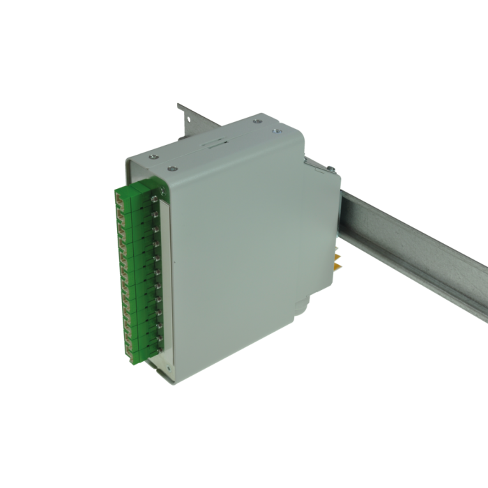
tBL® - DIN rail splice housing SM 6x E2000 APC OS2, splice ready prepared
Article ID
TBL-H12-06E2A9AS
tBL® - DIN rail splice housing SM 6x E2000 APC OS2, splice ready prepared
| Pre-mounted | 6 E2000 APC adapters SM 6 E2000 APC Fiber pigtails 9/125µ OS2 2.0 meters 12 x Colors, splice ready prepared 6 Crimp Splice protectors 1 Splice cassette 1 Splice holder 1 Cabel entry vertical 1 Mounting clip (for mounting on rail housing) 1 Gland M20 for cable entry |
| Alternative pre-mounted |
TBL-H12-xxE2A9Ayz (see below) |
| xx | (01 - 12) quantity of adapters |
| y | (S)plice ready prepared |
| z | With(O)ut Crimp Splice protectors |
tBL® - DIN rail splice housing, basic housing
| Housing | Alu-sheet, 1 mm |
| Dimensions | 141.4 x 141 x 42.8 mm |
| Colour | powdered in RAL 9005 (black) |
tBL® - FO Front panel 3U 8HP 12x SC Simplex for DIN rail splice housing
| Front panel | Alu-sheet |
| incl. labeling strip | |
| Configuration | Attachment up to 12x SC simplex or 12x E2000 Simplex adapters |
E2000™ APC Simplex Adapter, green
| Type | E2000 APC Simplex Adapter with flange |
| Flansch | Plastic, 3.5mm material thickness |
| Captive metal nuts | |
| Standardisation | IEC61754-15 |
| TIA 604-16 | |
| RoHS | |
| Connector class | coupling Adapter |
| Number of connectors (A) | 1 |
| Connector type (A) | E2000™ |
| Alignment technology | Ceramic precision sleeve (Zirkonia Zr02) |
| Delta insertion loss | < 0.1dB |
| Mating cycles | min. 1000 |
| Connector color (A) | green |
| Sleeve material | ceramic |
| Fiber type | Singlemode (SM) |
FO E2000 APC connector tde class C for 09/125µ fiber
| Type | E2000 APC |
| Ferrule | Ceramic |
| Ferrule Hole | 125.5 µ |
| Ferrule Concentricity | ≤ 0.6 µ |
| Connector Colour | Green |
| Lever Colour | Green |
| Boot Colour | Green |
| Manufacturer | RDM |
| Fiber | Type | Wavelength | Insertion loss typ. | Insertion loss max. | Return loss min. |
|---|---|---|---|---|---|
| 9/125µ | E2000 APC | 1550 nm | ≤ 0.20 dB | 0.45 dB | 70 dB |
FO Cables
| Tight Buffer | Low smoke (IEC 61034 and EN 50268) and free of halogens (LS0H) |
| Non corrosive after IEC 60754-2 and EN 50267 | |
| Flame resistent after IEC 60332-3C and EN 50266-2-4 | |
| Completly dry design | |
| Free from metal, no grounding problems and potential differences | |
| Tight Buffer for simple and direct connector mounting |
| Fiber Count | 1 (Tight Buffer) |
| Core-Ø | 0.9 mm |
| Coreweight | 1 kg/km |
| Min. Bending radius - Installation | 30 mm |
| Min. Bending radius - Operation | 30 mm |
| Removal | 1500 mm |
|
Fire load |
0.15 MJ/m |
|
Temperature range - Installation |
-5 to +50°C |
|
Temperature range - Operation |
-20 to +60°C |
|
Temperature range - Transport / Lagerung |
-25 to +70°C |
Corning FO Ultra SMF-28® 09/125µ OS2 singlemode fiber
| Type | Corning Ultra SMF-28® 09/125µ OS2 singlemode fiber |
| Maximum Attenuation | At 1310 nm max. 0.32 dB/km At 1383 nm max. 0.32 dB/km At 1490 nm max. 0.21 dB/km At 1550 nm max. 0.18 dB/km At 1625 nm max. 0.20 dB/km |
| Attenuation vs. Wavelength |
Range: 1285 - 1330 mm; Ref. λ: 1310 nm; Max. α Difference: 0.03 dB/km Range: 1525 - 1575 mm; Ref. λ: 1550 nm; Max. α Difference: 0.02 dB/km |
| Macrobend Loss | Mandrel Radius: 10mm; Number of Turns: 1; Wavelength: 1550nm; Induced Attenuation: ≤ 0.50 dB Mandrel Radius: 10mm; Number of Turns: 1; Wavelength: 1625nm; Induced Attenuation: ≤ 1.5 dB Mandrel Radius: 15mm; Number of Turns: 10; Wavelength: 1550nm; Induced Attenuation: ≤ 0.05 dB Mandrel Radius: 15mm; Number of Turns: 10; Wavelength: 1625nm; Induced Attenuation: ≤ 0.30 dB Mandrel Radius: 25mm; Number of Turns: 100; Wavelength: 1310nm, 1550nm, 1625nm; Induced Attenuation: ≤ 0.01 dB |
| Point Discontinuity | Wavelength: 1310 nm; Point Discontinuity: ≤ 0.05 dB Wavelength: 1550 nm; Point Discontinuity: ≤ 0.05 dB |
| Cable Cutoff Wavelength (λccf) | λccf ≤ 1260 nm |
| Mode-Field Diameter | At 1310 nm = 9.2 ± 0.4 µm At 1550 nm = 10.4 ± 0.5 µm |
| Dispersion | At 1550 nm = ≤ 18.0 [ps/(nm*km)] At 1625 nm = ≤ 22.0 [ps/(nm*km)] |
| Zero Dispersion Wavelength (λ0): 1304 nm ≤ λ0 ≤ 1324 nm Zero Dispersion Slope (S0): ≤ 0.092 ps/(nm² *km) |
|
| Polarization Mode Dispersion (PMD) | PMD Link Design Value = ≤ 0.04 ps/√km Maximum Individual Fiber = ≤ 0.1 ps/√km |
| Fiber Curl | ≥ 4.0 m radius of curvature |
| Cladding Diameter | 125.0 ± 0.7 µm |
| Core-Clad Concentricity | ≤ 0.5 µm |
| Cladding Non-Circularity | ≤ 0.7% |
| Coating Diameter | 242 ± 5 µm |
| Coating-Cladding Concentricity | < 12 µm |
| Environmental Test | Test Condition | Induced Attenuation 1310 nm, 1550 nm & 1625 nm |
|---|---|---|
| Temperature Dependence | -60°C to +85°C | ≤ 0.05 |
| Temperature Humidity Cycling | -10°C to +85°C up to 98% RH | ≤ 0.05 |
| Water Immersion | 23°C ± 2°C | ≤ 0.05 |
| Heat Aging | 85°C ± 2°C | ≤ 0.05 |
| Operating Temperature Range | -60°C to +85°C |
| Proof Test | The entire fiber length is subjected to a tensile stress ≥ 100 kpsi (0.69 GPa). |
| Length | Fiber lengths available up to 63.0 km/spool. |
| Core Diameter | 8.2 µm |
| Numerical Aperture | 0.14 |
| Effective Group Index of Refraction | 1310 nm: 1.4676 1550 nm: 1.4682 |
| Fatigue Resistance Parameter (nd) | 20 |
| Coating Strip Force | Dry: 0.6 lbs (3N) Wet: 14 days room temperature: 0.6 lbs (3N) |
| Rayleigh Backscatter Coefficient (for 1 ns Pulse Width) | 1310 nm: -77 dB 1550 nm: -82 dB |
tBL® - splice cassette for DIN rail splice housing
| Type | splice cassette for DIN rail splice housing |
| Material | sheet steel |
| Colour | powdered in RAL 9005 (black) |
| Configuration | uo to 2x 12 splices |
FO Splice holder for 12x crimp splice protectors
| Type | FO Splice holder for 12 x Crimp splice protectors |
| Dimensions | 40 x 26 x 6 mm |
| Material | Bright ABS, similar RAL 1013 |
FO crimp splice protector
| Type | Crimp splice protector |
| Dimensions | 31 x 3 x 1 mm |
| Delivery time | 5-10 working days |
|---|---|
| Manufacturer | tde |
| Systems | tBL® - tde Basic Link (FO Enclosures) |
| Category | FO DIN rail splice module |
| Mediaobjects | |
| Connector type (side 1) | E2000 APC |
| Fiber type | 09/125 µm OS2 |
| Type | E2000 APC |
| Adapter color | Grün |
| Material | Stahlblech |
| Patch panel type | tBL® - FO DIN Rail Module |